Friday 1 November 2013

A Tree on the Track

On Monday 28th November 2013, we woke up to find a slight setback in the garden railway development. A large pine tree has shed its upper half onto our 200 year old wall and part of the garden. An apple tree had disappeared completely, but we hoped that the railway might just have been protected by the wall.
Looking down the bank towards the fallen tree.
 
Looking up the bank towards the fallen tree.

The fallen tree was removed on the following Friday morning. I have to say that the team from Elmbridge council did a splendid job, and were careful to avoid any further damage to the wall or the railway.

The tree being cut up and removed
Within an hour of the team arriving to cut up and remove the tree, I had the first train running. The kink in the foreground of the picture was the only obvious damage to the railway. The wall wasn't so lucky.....

The first train after removal of the tree.

Friday 18 October 2013

Fitting DCC Decoder to a Bachmann Collett 0-6-0 with Cast Metal Tender

Going through my Dad's old model railway bits, I found a K's white-metal kit for a Dean Goods 0-6-0. The loco was incomplete, but one of the Collett 0-6-0's on our local branch line in the 1960s was fitted with the tender from a Dean Goods, and I had a spare Bachmann Collett 0-6-0. This model's destiny suddenly changed to one with a future as 2218.

This particular Bachmann loco was unusually a very poor runner, moving fitfully and stalling frequently. Adjusting the pick-up contacts had not resulted in any improvement, so I experimentally (ie as an unmaintainable lash-up) fitted pick-ups in the tender and two sprung electrical contacts between the tender and loco. But it was cumbersome and difficult to wire, and didn't make it run any  better, so it was removed. And it has sat in a box for a couple of years waiting for another idea.

Now that the garden railway uses digital control (DCC), I have been gradually fitting the appropriate locos with decoders. The older Bachmann Colletts have no space for a decoder in the loco without cutting metal, but it was clear that the floorless white-metal tender could easily be made to house a decoder with four linking wires to the loco. To alleviate the inconvenience of having them permanently coupled, I would use a connector. I produced a design and proceeded with an experimental assembly. Wiring was again extremely difficult, and the force required to separate the connector was impossible to apply where it was needed. So back to the drawing board again.

It then struck me that if the decoder was fitted to the loco with wires of the right length and slid into the tender during coupling, the difficulties would all be resolved. Wiring would be more straightforward (there would be none permanently in the tender), the loco and tender would be easily separable, and no connector would be needed.

First I made an insulated box to take the decoder. I used 30 thou plastikard. It must be wide and high enough to easily fit the decoder, and reasonably long. About twice the length of the decoder (if possible) seems about right. The bar across the bottom end (end A in the first photo) is to stop the decoder falling all the way through while still allowing air flow, and the packing under the entry end (end B) is as thick as is necessary to get the entry angle correct. To clear the wheels, the overall width should not be more than about 12mm for 00, which restricts the choice of decoders. I used a TCS M1, which comes fitted with a protective insulating sleeve. If you use an unsleeved decoder, you should fit a sleeve for protection.
 
The decoder box before installation in the tender.
The box was then fitted in the tender and held in place with a suitable adhesive. Check that the sleeved decoder and cables slide in easily, and the wheels turn freely.
  
The decoder box in place under the tender.
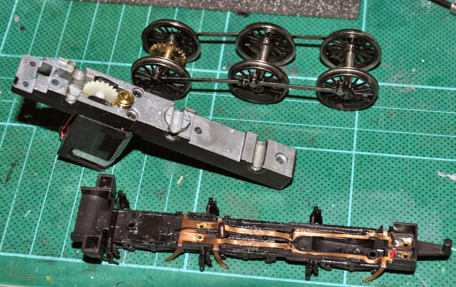
Now remove the loco body by undoing the two screws at front and rear of the chassis. Then loosen the central chassis screw, and carefully remove the keeper plate and wheelset from the main chassis block. To fully separate them, you need to cut the red and black wires leading to the motor. 
 
The three main chassis sub-assemblies.

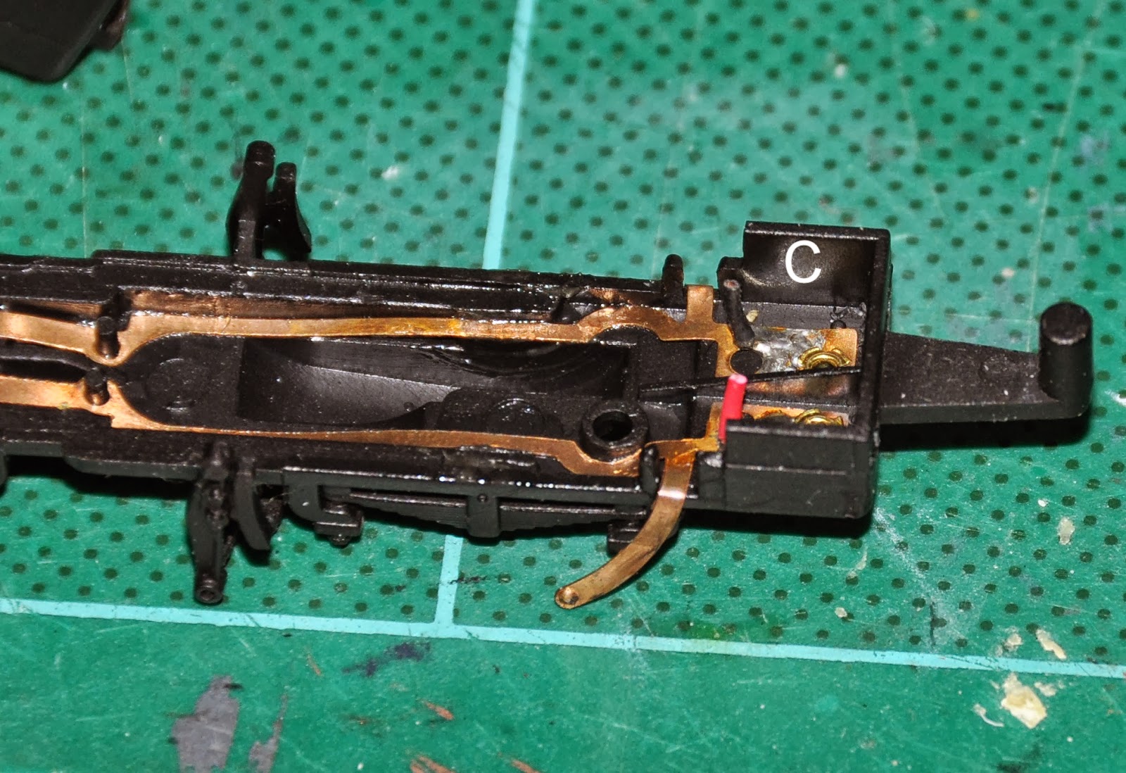
Quickly and carefully (to avoid melting plastic), unsolder the red and black wires both at the motor and at the metal contact strip attached inside the keeper plate at C in the picture below. Drill two tiny holes each side of the tender hook, each just big enough to take one decoder wire. Cut short and sleeve the unused decoder wires (blue, yellow, white). Fit any protective sleeving you think necessary to protect the wires from chafing. Feed the decoder wires through the holes, with red and black closest to the metal contact strips inside, to which they will be soldered, and red on the right from behind when the wheels are down. Allow them to slide in and out while trying the position of the decoder until it is about half-way down its box with he tender coupled. When you are happy that it is just right, unthread the orange and grey wires to avoid damage, then trim the red and black wires to length and solder carefully to the contact bars.
 
Part of the keeper plate showing solder terminals C and tender hook. 

Re-thread the orange and grey wires into the keeper plate, then thread them through the square hole in the main chassis block, carefully re-fit the wheels and keeper plate ensuring the six contacts are correctly located behind the wheel rims, and tighten the middle screw. Run the orange and grey wires up to the motor terminals using the same route as the old red and black wires, trim and solder in place. Note that space is very tight, so correct routing of the wires is critical to avoid damage.
 
The finished "decoder tail".

You can now check there are no short circuits, especially from red to black or orange to grey. If ok, test on the track, and if still ok, refit the body and tighten the front and rear screws.
 
Loco and tender coupled together. The wires will be painted black.

A similar principle could be applied to other locos with limited space for a decoder, providing (a) it has a tender and (b) the tender has a suitably located space for a decoder box. Unfortunately, this rules out the majority of limited-space locos, which are tank engines.
 
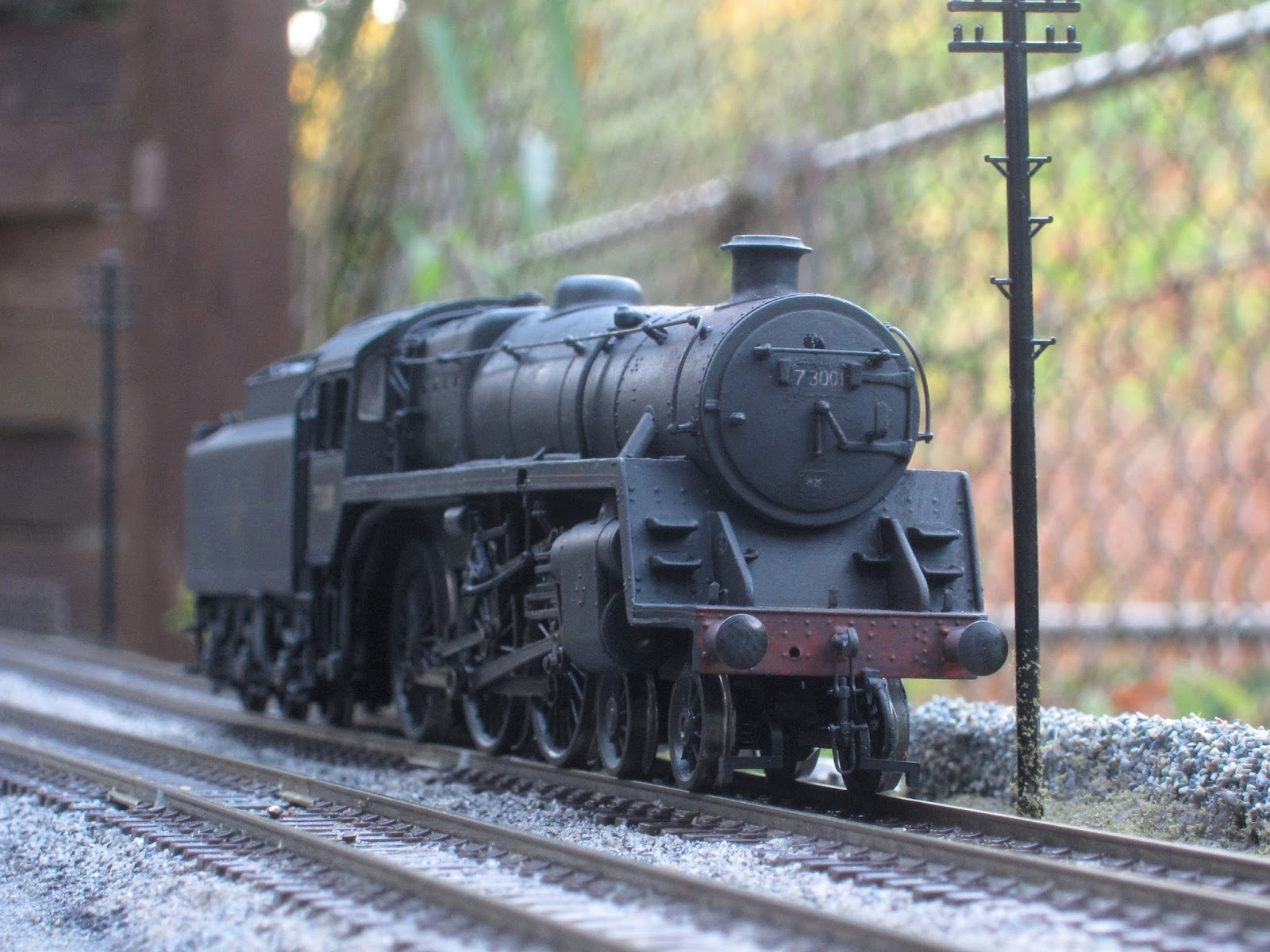
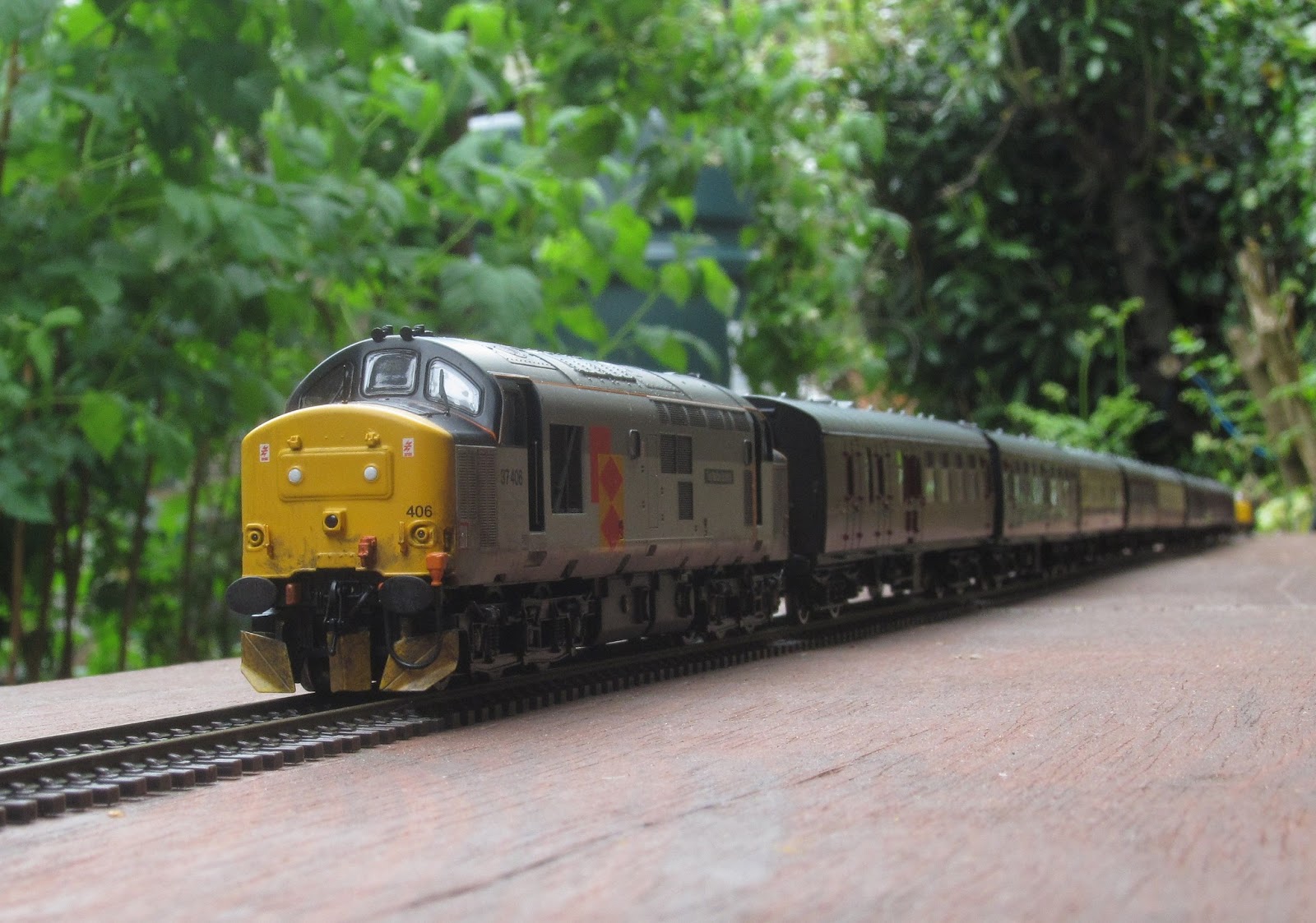
The following day, the engine was given a test run in the garden. The heavy rain showers  meant that the trackbeds were saturated, but she still managed 8 coaches up the 1 in 50, with only occasional short bouts of slipping. The actual total weight of the coaches used was 1020g, which on a 1 in 50 gradient requires, ignoring friction losses, a pulling force (or tractive effort) of 20g. Scaled up 76 times to full size (i.e. multiplied by 76 cubed because weight or force is proportional to volume) gives a figure of about 20,000lb. For comparison, the quoted theoretical tractive effort for a real engine of this class is 20,155lb - a pretty good correlation!
 
2218 under main line test. She still needs some painting, detailing and renumbering.
A bonus result of this task was that when I removed the keeper plate, I found that the gears, axles, and sprung centre wheelset bearing were all packed with a thick grease, most of which had hardened to the consistency of candle-wax. It's not surprising it was a poor runner! As much as possible of the grease was scraped out, a little light oil applied, and it is now one of the sweetest of runners.


Saturday 14 September 2013

Planting for a 00 Garden Railway.

My garden railway has been built based on the principle that it will blend in with the garden, and the trains running on it will "look right". It would be impractical to add 00 scale scenery as I would with an indoor layout, so it is important to choose the right vegetation around the railway.

The first place I looked was in the "Alpines" section of the garden centre. The plants in this section are generally small and slow-growing, so they shouldn't dwarf the trains, and shouldn't require too much maintenance. One of the early finds is described below.

Arenaria balearica is a low, spreading plant with tiny leaves. It flowers on short stems in early summer, and retains its leaves all year. It likes well-drained soil, sun or part shade, and is  drought-resistant. It is ideal for providing ground cover close to ground-level trackwork, reducing the chance of earth splashing over the rails when it rains.


Arenaria balearica
I have just found this post sitting waiting patiently as a "draft post". Although it is a bit shorter than originally intended, it might be useful to someone, so her it is! Perhaps I will continue the topic in a later post.

Monday 9 September 2013

Scenery!

One of this summer's activities has been to add a bit of scenic interest to the sections of railway not integrated with the real garden. This means, principally, adding fencing, telegraph poles and other items on the raised sections along the railway fence and the neighbours' fence. Having just completed a post on the recent viaduct construction work, I realised I had nowhere mentioned this scenic work done at the opposite end of the railway. So here are a few pictures.

A 4MT 2-6-0 approaches the tunnel around a banked curve.

New fencing is visible to the right of the picture.


Approaching a farm occupation crossing.

A vertical pole shows that the curves really are banked.

Bridge over a (to date) imaginary river

73001 runs light past one of the "new" telegraph poles.
The tomatoes are doing well!

 
"Tornado" races along a newly-fenced section of track.

On the curve from the tunnel to the railway straight.

An evening auto-train stops at the halt.

More fences and poles.

Who left that gate open?!!

The 7.10pm Bath - Templecombe on 5th March 1966?


Completing the Circuit

It has always been part of the long-term plan to provide a complete circuit by extending the track across the lawn, through the rose bed, and through a shed behind the clothes-drying area and greenhouse to meet the existing track by the neighbours' fence. This was agreed in principle by the Garden Planning Authority (GPA)*, subject to a number of conditions:
  • The lawn crossing must not impede mowing, other forms of gardening, garden parties, access to outbuildings (sheds), or any other current garden activity.
  • The route through the rose bed must be sympathetic with the cosmetic and artistic needs of the garden, and must not impede planting and maintenance activities.
  • It must be possible still to use the clothes-drying area for its intended purpose.
  • Any broken or unsightly fence panels exposed by ground clearance must be rectified. 
  • Detailed designs must be discussed and agreed with the GPA prior to implementation. Aspects to be considered will include appearance, practicality, maintenance requirements, and effect on other garden users.
The design complies with these requirements by means of the following features:
  • The lawn is crossed by a multi-arch viaduct (loosely based on Glenfinnon, Shepton Mallett and similar). This includes a 6-foot long section which is easily removable. The viaduct traces a graceful curve in sympathy with the garden.
  • The route through the rose bed has been agreed. Several roses have been transplanted to a better locations, and "sacrosanct" plants identified.
  • The clothes dryer has been moved forward to make room for a 6' deep shed while remaining screened from the house by the trellis.
  • Three panels and one post of the neighbour's fence have been replaced, and the remainder painted.
 
A first trial assembly of viaduct components.

First tentative steps onto the lawn.

New fence panels behind the site of the still-to-be-built shed.
Optimising the route.
The lawn is crossed!
Marking the route through the rose bed.
First passenger train (on temporary rails).
Another trial train.

A Dragonfly checks out the new additions.

The viaducts with painting under way.
A panoramic view. The removable section is still in white primer.


Notes.
*  The current composition of the Garden Planning Authority (GPA) is as follows: Chairman; co-opted as required. Display and horticultural authority; Penny. Technical authority (non-horticultural); me. Consultants; Jan and Gerald.

Sunday 7 July 2013

Playing to an audience (again)

Following the success of the garden open day in June, the garden railway was looking forward to  Sunday's garden party. All went well for most of the day, with somewhere between 20 and 30 of our guests opting to take a turn at driving a train. Thomas (now fitted with a Bachmann Jinty chassis) ran reliably from end to end with a train of three coaches. The only warning of problems to come was an occasional unreliability of the points on the removable panel above the tunnel.

When most of the guests had gone, James and the formula 1 team stayed to continue the railway running session, and it wasn't long before there was a request for the two sound-equipped locos, one steam and one diesel. These were duly provided, and that's when things started to go badly wrong. First, the "Briannia" ran away, refusing to respond to any commands to stop. Then a spate of spurious derailments started. The track was examined for debris, and the computer was reset, to no avail. The investigation will continue tomorrow, but it's worth noting a few observations.
  • Three locos were running simultaneously; Thomas, and sound equipped 37 and Britannia.
  • Two controllers were in use, my iphone for Thomas and the Brit, and my ipad for the 37.
  • A number of wood ants were run over by trains
  • The rail gap between the quarry points and the viaduct straight had increased to about 2mm.
  • The rails were noticeably dirty
  • The removable crossover had been in place for over a month, and signs of unreliability had started a few days ago.

Tuesday 18 June 2013

Reopening the Quarry

The quarry sidings, which have been derelict for almost a year now, have been brought back into use. This has involved removing all of the loose rocks, earth-slips, and fallen twigs and leaves, and stabilising the gaps between the rocks to reduce the risk of further earth slips. The smaller loose rocks will then be cemented in place to allow future leaf removal to be mechanised. The three live-frog turnouts giving access to the quarry from the main line have been replaced with dead-frog, which I have wired so that they do not require electrical switching when the route is changed. This will reduce the need for delicate cleaning before each operating session. The disadvantage, of course, is that short-wheelbase locos are now more likely to stall on the point frog. There is also a risk that some tweaking of frogs may be required to avoid momentary short-circuits as a loco crosses the frog.

The picture shows a Pannier tank loco testing the track at the lowest point in the quarry. It looks as if the track in front of the loco has been damaged by a rock-fall!
 
The lowest point of the quarry.
The second picture shows the loco testing the quarry siding climbing back up the 1 in 25 gradient out of the quarry. The sparse vegetation visible in both pictures is growing naturally, one of the benefits of a garden railway.

Climbing the 1 in 25 gradient out of the quarry.

Monday 3 June 2013

The Earth Moved

Something funny happened over the winter to a length of my track. The sharp (actually, it's 5' radius) curve about to be traversed by the cat in the picture, got longer!

I first noticed that the two rail joints on the curve were getting wider. For a while, it was still passable to trains. But by the time I did something about it, the gap was almost the length of a fishplate.

Mac heads for the affected curve.
What I found on investigation was that the rubbercrete capping had separated from the brick base in this area. Why it had stretched I don't know, but no longer bonded to the bricks there was no stopping it!


The "slipped" curve after corrective work to the trackbed, and before the track was relaid.

On Monday, the track was relaid on the down main line, and trains were running again, single-line, with a 20mph speed limit until the ballasting was complete.

A ballast train approaches the new section of track.

An overhead view of the site.

Ballasting in progress.

The team

You may have noticed that the new track is being laid with some precision on a narrow strip of rubberised cork, whereas the old track was on a wide strip of closed-cell foam. I don't pretend that this is a new method of track construction, but it is new to this railway, and aims at eliminating some of the disadvantages of the old method. Whether it brings with it any new problems, remains to be seen.

Advantages of new method:
  • Curves are made with a series of 100mm straight lengths end to end, allowing curves and transitions to be laid out and adjusted accurately before track is laid.
  • Banking on curves can be set up and measured accurately before track is laid.
  • More rigid than foam, so track pins do not cause sleepers to bend in the middle,
  • Accurate width facilitates a neater ballasting job.


Sunday 2 June 2013

Preparing for the Open Day

Open day? Whoever heard of an open  day for a model railway? Well, it looks as if we are having one next Saturday.

Every year, an "Open Garden weekend" is organised to raise money for our local hospice. A minimum of six gardens are open each day, and programmes are available at the reception desk, giving directions and a map for each garden. This year it includes our garden, railway and all!

And what am I doing in preparation? Principally, running trains and operating points and signal, to identify any areas of unreliability, then (if practical) fixing them. And while I'm running these trains, I might as well photograph them.

First we have a pannier tank with a single coach. It must be empty stock, or a special working, as the coach has no guard's compartment.

Pannier tank on the Railway straight.
Next we have several shots of Evening Star hauling 10 coaches. It just managed up 1 in 50 on straight track, but stalled on the long curve. And on a couple of occasions, the force exerted by the engine to pull the heavy train up the gradient on a curve was too much for the front coaches, and the lateral force pulled it off the rails.

"Evening Star" bursts out of the tunnel
One of the benefits of photographing the models is that errors and omissions are suddenly glaringly obvious. For example, where I this engine's vacuum brake pipe?

"Evening Star" leaves the cutting above the quarry.
The other thing that's glaringly obvious in the pictures is the red bus-wire following the track. I've now been around with the brown camouflage paint!

"Evening Star" rushes past the quarry.
The railway currently has one operating signal, sited on he viaduct and indicating that the route is correctly set for  "clockwise" trains. There is wiring at the other end of the viaduct for an equivalent signal for anticlockwise trains.


"Evening Star" approaching the viaduct.
"Evening Star arrived on our railway hauling an enthusiasts' special. The return train was worked by a pair of Scottish 37s, which are seen waiting to couple onto the train.

37406 "The Saltire Society" and 37417 "Highland Region".

37406 is the train engine....


....with 37417 piloting,

Meanwhile, life in the village continues as normal, with the pub landlady carrying a plate of food out for "old George", as the post van arrives with the afternoon delivery.

The pub below the viaduct.
A special guest for the village fair on 9th June waits in the escape siding next to the quarry. The railway's financial controller has jokingly suggested offering this loco for sale on ebay as "DCC ready". Well, it's a static model, so it is fitted with all the decoders needed to fulfil this function - i.e. none.
A visitor from another age.

70040 "Clive of India" thunders up the 1 in 50 past waiting 4F 44560.
And finally, the bit you all really want to see, if the trains didn't keep getting in the way. Flowers!

Working on the "garden" bit of the garden railway.

Note: The circular flat area between the flower trough and the viaduct was purpose-built three years ago for the hexagonal gazebo used for the bar at the annual garden party. The entrance is via the grass slope in the foreground, with the trough moved elsewhere of course. The size and shape of the gazebo dictated the route the railway took in this area, and the need for the viaduct to be curved.

And finally....  At the start of an operating session, the track cleaning train disappeared into the tunnel and didn't emerge at the other end. Another engine was sent in to push, without success. So the tunnel slabs and liner were removed, and the cause of the problem immediately became clear!

There's not room for both of us in this tunnel!