Tuesday, 18 June 2013

Reopening the Quarry

The quarry sidings, which have been derelict for almost a year now, have been brought back into use. This has involved removing all of the loose rocks, earth-slips, and fallen twigs and leaves, and stabilising the gaps between the rocks to reduce the risk of further earth slips. The smaller loose rocks will then be cemented in place to allow future leaf removal to be mechanised. The three live-frog turnouts giving access to the quarry from the main line have been replaced with dead-frog, which I have wired so that they do not require electrical switching when the route is changed. This will reduce the need for delicate cleaning before each operating session. The disadvantage, of course, is that short-wheelbase locos are now more likely to stall on the point frog. There is also a risk that some tweaking of frogs may be required to avoid momentary short-circuits as a loco crosses the frog.

The picture shows a Pannier tank loco testing the track at the lowest point in the quarry. It looks as if the track in front of the loco has been damaged by a rock-fall!
 
The lowest point of the quarry.
The second picture shows the loco testing the quarry siding climbing back up the 1 in 25 gradient out of the quarry. The sparse vegetation visible in both pictures is growing naturally, one of the benefits of a garden railway.

Climbing the 1 in 25 gradient out of the quarry.

Monday, 3 June 2013

The Earth Moved

Something funny happened over the winter to a length of my track. The sharp (actually, it's 5' radius) curve about to be traversed by the cat in the picture, got longer!

I first noticed that the two rail joints on the curve were getting wider. For a while, it was still passable to trains. But by the time I did something about it, the gap was almost the length of a fishplate.

Mac heads for the affected curve.
What I found on investigation was that the rubbercrete capping had separated from the brick base in this area. Why it had stretched I don't know, but no longer bonded to the bricks there was no stopping it!


The "slipped" curve after corrective work to the trackbed, and before the track was relaid.

On Monday, the track was relaid on the down main line, and trains were running again, single-line, with a 20mph speed limit until the ballasting was complete.

A ballast train approaches the new section of track.

An overhead view of the site.

Ballasting in progress.

The team

You may have noticed that the new track is being laid with some precision on a narrow strip of rubberised cork, whereas the old track was on a wide strip of closed-cell foam. I don't pretend that this is a new method of track construction, but it is new to this railway, and aims at eliminating some of the disadvantages of the old method. Whether it brings with it any new problems, remains to be seen.

Advantages of new method:
  • Curves are made with a series of 100mm straight lengths end to end, allowing curves and transitions to be laid out and adjusted accurately before track is laid.
  • Banking on curves can be set up and measured accurately before track is laid.
  • More rigid than foam, so track pins do not cause sleepers to bend in the middle,
  • Accurate width facilitates a neater ballasting job.


Sunday, 2 June 2013

Preparing for the Open Day

Open day? Whoever heard of an open  day for a model railway? Well, it looks as if we are having one next Saturday.

Every year, an "Open Garden weekend" is organised to raise money for our local hospice. A minimum of six gardens are open each day, and programmes are available at the reception desk, giving directions and a map for each garden. This year it includes our garden, railway and all!

And what am I doing in preparation? Principally, running trains and operating points and signal, to identify any areas of unreliability, then (if practical) fixing them. And while I'm running these trains, I might as well photograph them.

First we have a pannier tank with a single coach. It must be empty stock, or a special working, as the coach has no guard's compartment.

Pannier tank on the Railway straight.
Next we have several shots of Evening Star hauling 10 coaches. It just managed up 1 in 50 on straight track, but stalled on the long curve. And on a couple of occasions, the force exerted by the engine to pull the heavy train up the gradient on a curve was too much for the front coaches, and the lateral force pulled it off the rails.

"Evening Star" bursts out of the tunnel
One of the benefits of photographing the models is that errors and omissions are suddenly glaringly obvious. For example, where I this engine's vacuum brake pipe?

"Evening Star" leaves the cutting above the quarry.
The other thing that's glaringly obvious in the pictures is the red bus-wire following the track. I've now been around with the brown camouflage paint!

"Evening Star" rushes past the quarry.
The railway currently has one operating signal, sited on he viaduct and indicating that the route is correctly set for  "clockwise" trains. There is wiring at the other end of the viaduct for an equivalent signal for anticlockwise trains.


"Evening Star" approaching the viaduct.
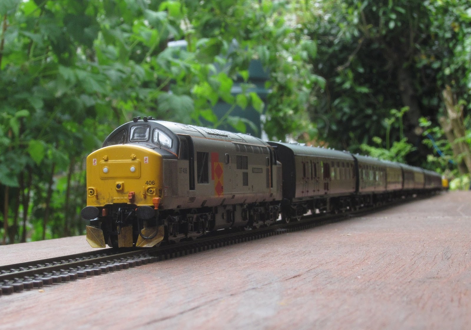
"Evening Star arrived on our railway hauling an enthusiasts' special. The return train was worked by a pair of Scottish 37s, which are seen waiting to couple onto the train.

37406 "The Saltire Society" and 37417 "Highland Region".

37406 is the train engine....


....with 37417 piloting,

Meanwhile, life in the village continues as normal, with the pub landlady carrying a plate of food out for "old George", as the post van arrives with the afternoon delivery.

The pub below the viaduct.
A special guest for the village fair on 9th June waits in the escape siding next to the quarry. The railway's financial controller has jokingly suggested offering this loco for sale on ebay as "DCC ready". Well, it's a static model, so it is fitted with all the decoders needed to fulfil this function - i.e. none.
A visitor from another age.

70040 "Clive of India" thunders up the 1 in 50 past waiting 4F 44560.
And finally, the bit you all really want to see, if the trains didn't keep getting in the way. Flowers!

Working on the "garden" bit of the garden railway.

Note: The circular flat area between the flower trough and the viaduct was purpose-built three years ago for the hexagonal gazebo used for the bar at the annual garden party. The entrance is via the grass slope in the foreground, with the trough moved elsewhere of course. The size and shape of the gazebo dictated the route the railway took in this area, and the need for the viaduct to be curved.

And finally....  At the start of an operating session, the track cleaning train disappeared into the tunnel and didn't emerge at the other end. Another engine was sent in to push, without success. So the tunnel slabs and liner were removed, and the cause of the problem immediately became clear!

There's not room for both of us in this tunnel!


Wednesday, 22 May 2013

Along the Neighbours' Fence

...or "Some Recent Activity on the Garden Railway".


The previous post showed a train taking its first tentative steps on the new section of trackbed. This section has the boundary fence on one side, and the raspberry beds, then the greenhouse, then the drying green on the other. It also finds itself, due to the lie of the land, about 2ft above the ground. All of this conspires to make this section unsuitable for full integration with the garden as has been done elsewere, and the plan is to build it like a traditional model railway on a baseboard, with rudimentary scenery, and (if practical) limited weather protection.

The temporary track has now been extended along the full length of the new section, almost to the greenhouse. The next stage of the plan is real track, some scenery, and the weather protection!

The first train to reach the greenhouse.
The Dapol track cleaner should be a real time-saver for a garden railway, providing a built-in vacuum cleaner, railhead cleaning fluid applicator, railhead scrubber and railhead polisher. It sounds like a dream come true, but I haven't yet for various reasons managed to get the best out of it. It is however useful for clearing the cobwebs from the tunnel at the start of an operating session!

The cobweb-removing train emerges from the tunnel with a fine catch of webs.
As I have mentioned before, the crossover from single track back to double beyond the tunnel is laid on a thin base and can be removed as a complete module. This allows the turnouts, point motors, electronics and wiring to be taken indoors when not in use, for protection from the weather. Installation or removal only takes a few minutes, with eight rail joiners to be slid using fine-nosed pliers, and two electrical connectors to be mated or undone. The wiring is largely out of sight from the normal viewing direction, but stepping over into the narrow gap by the fence, it becomes clear that the railway company's electrical contractors, K.Watt & sons, of Voltstone, Ampshire are not very good at producing tidy wiring! A bit of lacing cord and some camoflage paint should improve things, however.

On the removable crossover module. From this side the wiring is unobtrusive...
... but from the fence, it looks a mess!
Right from the start of the railway project, there has been a strip of level concrete above the viaduct for a station platform. About a year ago, a platform was built, with embosssed plasticard facings and an infill of concrete-based floor screeding. It seemed a good idea at the time, but unfortunately the screeding did not stand up to the weather, and soon looked a mess. So it was removed, and since then there has been no platform. The new one uses the original facings, but has a new plastic top. Now it just needs station buildings and a signal box!

A ballast train passes the new station platform. The shelter is borrowed.
The final picture provides a privileged view of the control room. On the left of the shelf is the NCE equipment, (a 5A power supply / control module, an overload trip, and a USB interface). Connected to this via the USB interface is an old netbook computer, scrapped because its display stopped working, and an old 15" display from one of our early home computers. Running on the netbook is a free programme called JMRI. Hidden behind the netbook is a wi-fi access point / router made redundant by BT when they upgraded this area's brooadband to use fibre-optics, and the box high on the wall is a controller build by my father about 50 years ago, with all electronics removed except the transformer, thereby providing a 16V AC supply for accessories that need it. I hate throwing things away if they can be re-used!

Not shown in the picture is the actual control panels used by the engine drivers or signalman. These can be any Apple iphone, ipad, or ipod touch or any Android* smartphone, running either the free or the under-£10 version of applications called WiThrottle or Engine Driver*, and communicating with the netbook through a wi-fi local network. This means that operators can wander wirelessly anywhere in the area of the railway.

*note: I haven't yet tried it with "Engine Driver" and an Andoid device.

The Control Centre.

Sunday, 5 May 2013

Is it May Already?

I have just logged on and was horrified to find that my last post was a Christmas greeting! What has happened to the first four months of the year? Well, I suppose the three-week holiday and several long weekends away haven't helped. Then there's the training for last week's run (raised £2k for Parkinson's UK). Lots of gardening (we're opening to the public on 8th June under the local hospice's open garden scheme). Pretty poor excuses really. Oh - and I've been working on the garden railway!

Jobs done or in progress this year are:
  • Routine maintenance
  • Extension round the corner from the railway boundary to the neighbour's boundary
  • Complete automation of removable crossover module
  • Re-ballast, wire, signal and automate the viaduct
  • Get the railway wi-fi control network working reliably
  • Install a power bus and connect to track at reasonable intervals.
Maintenance. The worst things the winter has done other than the obvious dirt and corrosion are to remove some of my earlier experiments in ballasting, and to significantly widen the gap at some of the rail joints. This gap-widening is rather strange, and mainly occurs near the apex of some of the sweeping curves in the picture below. I can only assume that the trackbed is"stretching". It doesn't yet cause derailments, so I haven't done anythng about it, but will soon need to as the gaps are still increasing (so it's not thermal contraction of the rail).

A Spring test-train sweeps around the reverse curves.
The railway track-bed has now reached a point where although descending at 1 in 50, the ground is descending faster and the track is about 2 feet off the ground. This, the need for a bend, and the fact that too much straight concrete viaduct gets boring, led to the decision that the next section of trackbed would be timber. This also gives some potential for tradional layout scenery, though weather proofing or protection could be interesting. The picture below shows the general construction of the first 12 feet of new trackbase, and the transition from concrete. Since the picture, a further 12 feet have been added.

A new section of wooden baseboard (paint still wet), and the transition from concrete.
 When I'm working in the garden, I am often visited by Mac the Cat, who likes company.

Hello. Need any help?

This ballast needs a good scratch.

Mmm, I like this nice smooth cat-path.
In the foreground of the ballast-scratching picture can be seen the viaduct, complete with its new ballast job, and with the points automated and a signal fitted. I haven't yet got round to proper painting and weathering.

While we were in the garden over Easter, I noticed some unusual motive power for the Waterloo - South Western main line. This was a result of the closure of Reading for major rework.

A diverted First Great Western HST heads for London Waterloo.
Given the opportunity to play with a brand new sound-fitted Britannia, what could I do but accept? The sound is fairly realistic, but has a few flaws and is not as good in my ears as the Bachmann class 37.

Hornby Britannia 70040 "Clive of India", fresh out of the box.
And finally....  I laid some temporary track on the new section of baseboard "round the corner". And who was first along it, propelling the rail-head treatment vehicle? Why, it was Thomas of course!

Thomas covers new ground with the track-cleaner.

Tuesday, 11 December 2012

Sunday, 2 December 2012

Magnetic Couplings - Important Information

IMPORTANT INFORMATION

One of the best ways to kill a good idea is to not define standards early on, so that everyone does it slightly differently, and no two systems can work together. Examples include VHS & Betamax, mobile phone chargers, and many more. There is one critical parameter of the McBogle (also known as DOGRF) Mk.2 coupling that I haven't yet defined and will now attempt to do so. For two couplings to mate correctly, they must both have their N and S poles in the same orientation, so that on mating, N attracts S and S attracts N. Having made about a dozen of these couplings now to an arbitrary standard, I have measured which are the N and S poles and will define this as the McBogle Mk.2 magnetic coupling standard. In that way, any couplings you make should work with anyone else's, and vice versa.

The tools you need are an ordinary magnetic compass (and no, a GPS receiver won't work unless it includes a magnetic compass), and a bar magnet (one of the magnets you are using for the coupling will do). Glue your magnet to the end of a non-magnetic stick with the line between N and S in line with the stick. (If you are using the same magnets I did, then one of the two flat faces is glued to the end of the stick.)

Point the magnet end of the stick at the compass, and move it all the way round the compass. If the red (N) end of the compass needle points to your stick, then we will say that your stick ends in a N pole. (I'm not sure whether this is the normal convention, but that doesn't matter provided that everybody follows the method exactly as I have described it.) If the red (N) end of the compass needle points away from your stick, then your stick ends in a S pole. Mark your stick with either S or N at the magnet end, and the opposite at the other end. You can now use the magnet end of your stick to check the polarity of any coupling or magnet, bearing in mind that N and S are attracted, and N and N or S and S are repelled. Couplings can also be checked by ensuring they mate correctly with a known good one. A known good one can also be used to hold a new pair of magnets in position while they are glued to their "pipes". I will try to add some photos to make this clearer.

And which way round should the coupling magnets be? When looking at the end of a vehicle on the rails with a coupling fitted, the mating face of the right-hand coupling magnet should have its N pole toward you.

Finally, a VERY IMPORTANT SAFETY WARNING. If you bought your magnets from a reputable dealer, you will have been given some dire warnings. It is worth reiterating that these tiny magnets can cause life-threatening injuries if accidentally swallowed. So keep them in their original packaging until assembled, and don't leave them laying on the work bench. And don't fit them to anything that could be used by children. If you pass them to anyone else, also pass on the warnings too. It's all common sense really, but so easy to forget or ignore, with potentially serious consequences.