On 6th September 2011, a distinguished team of railway specialists was assembled to carry out the formal inspection of Phase 1 of the Garden Railway Project (GRP). The evening started with a tour of the railway in the inspection saloon, followed by a lineside viewing of several trains running specially for the occasion.
 |
| 34067 "Tangmere" with a Phase 1 Inspection special. |
The inspectors were given a copy of the Chief Engineer's pre-inspection report, and after satisfactory responses to several more questions, deemed the Railway to have passed its phase 1 inspection. The team then repaired to the house for a celebratory dinner.
It was pointed out that the loco that had pulled one of the GRP Phase 1 Inspection trains had earlier in the week pulled the "Atlantic Coast Express " on the big railway at the end of the garden, only a few yards from the GRP railway.
 |
| 34067 "Tangmere" passes our garden. |
For the Chief Engineer's report, see Annex 1 at the end of this post.
Quarry Siding
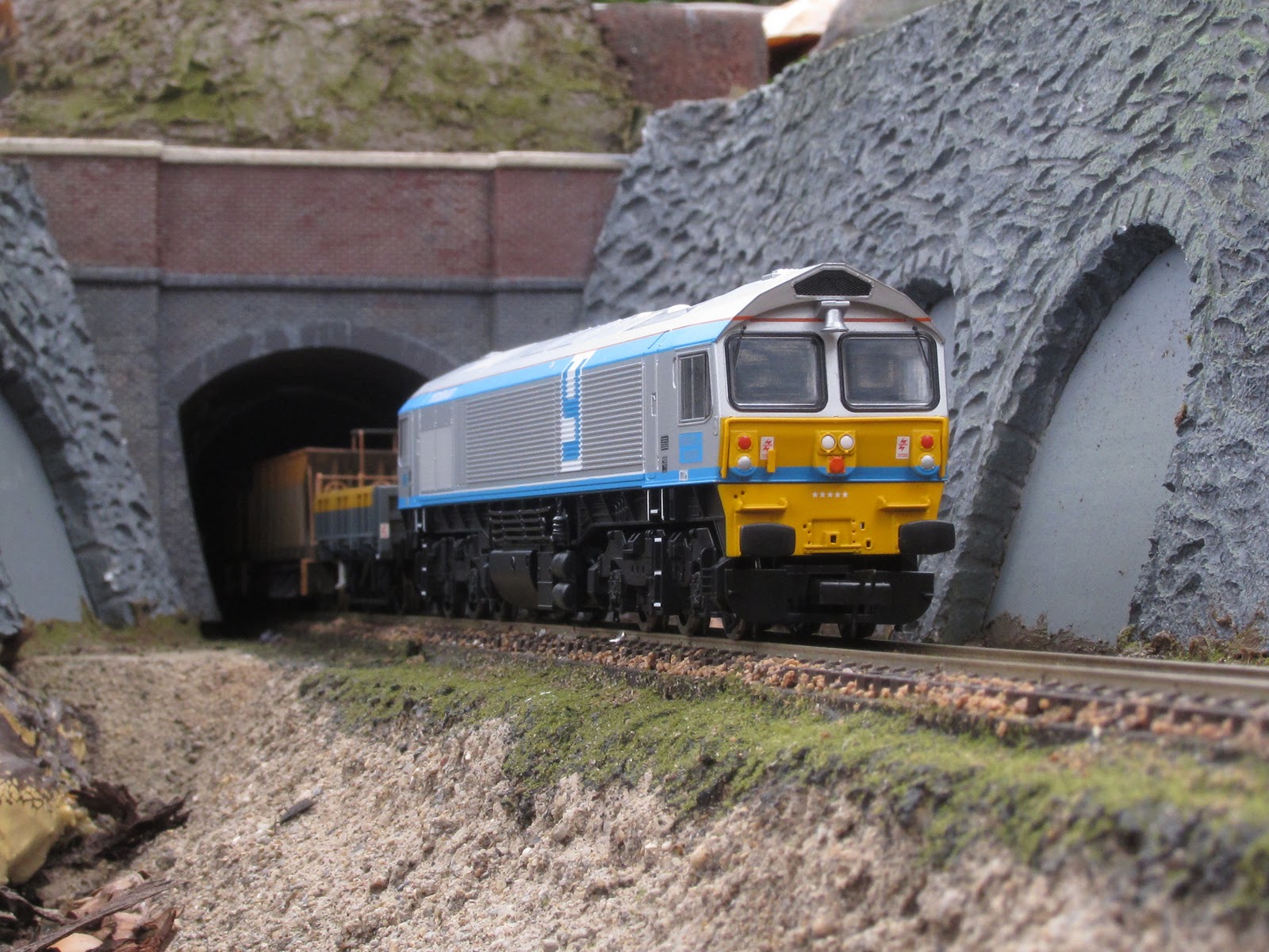
The trackbed is now in place for the main quarry siding. This leaves the main line just above the station, and is parallel with the main line for the length of the quarry. The gradient is level, so by the end of the siding, the main line is well above it. Track was laid temporarily to check levels and clearances, and this provided a photo-opportunity as a light engine on the main line passed our test engine.
 |
| A BR class 4 runs light down the main line from the tunnel past 37406, sitting simmering in the new siding. |
There are two additional turnouts at the entrance to the siding. The first will lead to a short spur, long enough for a shunting engine and 2 or 3 stone trucks. This will allow the quarry shunter to transfer wagons between the main siding and the quarry without the need for access to the main line. The second turnout will lead down to the quarry floor on a steep gradient.
 |
| The arrangement of turnouts at the quarry. |
As the shunting spur is unlikely ever to be used in model-land, I considered several alternative layouts including that shown below. I think I'll stick with the original though.
 |
| An alternative turnout arrangement, considered but rejected. |
Annex 1
GRP Phase 1 Inspection
Chief Engineer's Report.
The Garden Railway Project
The Garden Railway Project (GRP) is a project to construct a 00 scale railway in the garden of our house.
It was decided early in the project to divide the construction into phases. Phase 1 covers the section of track between the Bean Wigwam and the Oak Tree. Construction should then cease until the Chief Engineer is confident that the construction techniques have been seen to meet the environmental and other critical requirements.
During phase 1, the content of phase 2 will be defined.
Objectives for Phase 1
- Complete the detailed design of the phase 1 facilities.
- Construct trackbed from the Bean Wigwam to the gate, and lay track.
- Construct a removable section of track past the gate.
- Construct a trackbed past the Oak Tree, with space for a station platform, and lay track.
- Provide an electrical infrastructure for safe operation.
- Provide a plan for phase 2, and an initial outline for the entire project.
Requirements
- It shall be possible to run long trains, up to 12 coaches of the equivalent length in freight wagons.
- The removable section past the gate shall allow passage of items at least as wide as the gate itself.
- It shall be possible to open the gate with the removable section in place.
- The railway shall be safe
- The railway shall survive the annual climate with the minimum of maintenance.
Design Decisions
- The railway will be broadly based on the Somerset & Dorset around Midford, south of Bath.
- The removable section will be a viaduct, based on the one at Midford.
- There will be double track from the Bean Wigwam to the viaduct, becoming single on the viaduct and continuing single through the station.
- The station will be based on Midford.
- The rail will be Peco Streamline code 100, with “wood” sleepers.
- The line will use DC control for the locomotives. The wiring shall not preclude future conversion to DCC if so required.
- The topology of the garden necessitates gradients. The gradient shall not exceed 1 in 50 at any point on the main line
- There will be no curves sharper than 48” radius on the main line, and wherever possible the radius will be greater than 72”. Any turnouts on the main line will be Peco Streamline “large” radius (1524mm).
Achievement of Phase 1 Objectives
- The Requirements and Design Decisions are listed in the relevant sections of this document. Detailed design data and calculations are recorded in the Chief Engineer’s log book.
- The basic trackbed is in place from the Bean Wigwam to the gate, and about 4 metres of track is laid (single only). However, some sections are steeper than 1 in 50, the worst being short sections of 1 in 30. This severely limits the hauling capacity of the locomotives, and is not acceptable. Some sections of trackbed are also very uneven, and have been levelled with unsuitable materials (B&Q window frame sealant). The contractor has been instructed to relay at his own expense this entire section of trackbed, with a maximum gradient of 1 in 50 and using shuttered rubbercrete to provide an even trackbed
- The viaduct is complete with the exception of some detail painting, and the fitting of fencing. It has been designed and built, but not yet tested, to be weatherproof. It is reasonably easy to fit and remove. Electrical contact is currently through the fishplates, but ultimately a connector will be needed. The turnout is currently manually operated.
- The track is laid past the Oak Tree, and the basic structure of a station platform constructed but not yet fitted. In view of the delays in construction of the section downhill from the viaduct, the Board agreed to go ahead with constructing a section uphill from the Oak Tree, and a tunnel under the path. This work necessitated the removal of about six cubic metres of earth and construction of a rockery garden (quarry).
- A 230V mains to 16V AC transformer is fitted in the summer house. The 16V supply is taken to a weatherproof junction box on the Oak Tree, containing a DIN 6-way connector for a controller, and an output cable to the track just above the viaduct.
- The plans for phase 2 and beyond are given in the sections below.
Plans for Phase 2
The following activities will occur during Phase 2:
- Complete any unfinished Phase 1 work.
- Continue the track down the “end” (south) fence and the east fence of the garden (bordering next-door's garden). It should revert to double track soon after the tunnel. The proposed trackbed is pre-cast concrete lintels (Wickes).
- Provide a long siding and a quarry siding in the “quarry” (rockery). This was partially completed as extra work during Phase 1.
- Provide any necessary additional electrical infrastructure.
- Investigate the feasibility of remotely controlling the turnouts, and implement if practical.
- Design and implement a method for pre-assembling trains and “plugging in” to either end of the track. Ideally up to 12 coaches plus 2 locos, but it would be acceptable if a train this long was in two sections for transport.
- Operation and maintenance of the railway would greatly benefit from an “indoor” or under-cover section, where trains can be stored between uses during an operating session, and easily “put on” and “taken off” the running lines. It would also provide somewhere to store the removable sections, control equipment, tools, etc. The minimum requirement is a shed 8ft long, and sufficiently wide to provide the necessary access and storage. A review of potential locations concluded that the optimum location would be replacing the deep hedge behind the washing line, but other options are available. This should be investigated further during phase 2.
- Provide a plan for phase 3, and refine the outline plans for the entire project.
The target date for completion of phase 2 is Spring 2012.
Plans beyond Phase 2
It is an aspiration to complete a circuit of track around the garden. Preliminary surveys have shown that the two most likely options are:
- Complete the circuit with a removable section across the lawn, from just below the pond to just above the washing-line trellis
- Complete the circuit with a removable section across the lawn, in the vicinity of the cherry blossom shrub planted in an island in the lawn. This would connect along a raised track in front of the raised beds, following the stone slab path, and a raised track in the hedge behind the border on the east side of the garden.
A decision on which option to take will be needed during phase 3, or possibly late phase 2.
Conclusions
Phase 1 is largely complete, but is now undergoing major rework on the double-track section. Significant extra work was completed beyond the original Phase 1 objectives, including the quarry bank and the tunnel. Plans for phase 2 and beyond have been defined.
It is proposed that work commence on phase 2 at the discretion of the Chief Engineer, with immediate effect.