Thursday, 27 September 2012

Double-Heading.

It's an afternoon in early September, and everything is quiet at the lineside above Stoke Gurney. Suddenly, the silence is broken by the sound of a train appearing out of a cutting, its two locomotives working hard against the stiff 1 in 50 gradient. This is one of the last holiday trains of the season, bringing families from the midlands to south coast resorts. The sound reaches a crescendo as the train crosses the viaduct and whistles a warning for the short cutting to the quarry siding.

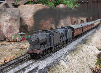
A double-headed holiday train climbs the 1 in 50 over the viaduct.
 
After a stretch of level track through the station, the two locos dig their heels in again for the final 1 in 50 climb past the quarry to the tunnel and the summit.


The two engines thunder up the quarry bank with their train.
 
As the train passes, the loco crews can be seen on their footplates, the fireman of the pilot engine still working hard to maintain a good head of steam. His work is nearly over though; after the tunnel, it's mainly downhill until they reach their destination.

The fireman of the pilot engine is working hard to keep a good fire
 
Another burst on the whistle , and the train disappears into the tunnel. Silence returns to the valley.
 
 ----------------
 
In reality, this was a test of some new facilities on the garden railway. The name Stoke Gurney was made up as I wrote, and will probably never be used again. The two engines did pull the train up the bank however, as can be seen at http://www.youtube.com/watch?v=ERe_CYS_4Tw&feature=youtube_gdata.
 
My reasons for the running session were:
 
  • To try the DCC controller in the garden after receiving a replacement power supply unit.
  • To test on something longer than the workbench test track these two ancient engines after fitting DCC decoders. The train engine was an Airfix model, bought by my father in the 1970s or early 80s. The pilot engine was a Hornby model bought through ebay as a wreck, the necessary repairs including new cab steps and a replacement mechanism salvaged from another Airfix 4F.
  • To try double-heading with DCC control and its new power supply. I didn't mess around with "consisting"; the two engines were driven with two independent "throttles" on a single ipad screen using the "iThrottle" application.
  • .. and while I was at it, to enjoy the sight of the train snaking up the reverse curves, over the viaduct, and through the tunnel, and record it for future reference.


Friday, 14 September 2012

Track Construction for a 00 Garden Railway.

(DRAFT)


Overview

 
General approach: Concrete or brick or building blocks, then a layer of rubbercrete, then roofing felt primer, then 3mm closed-cell foam, then peco flexible track pinned down on curves, then stone ballast held in place with diluted waterproof PVA and enclosing the foam. The straight section up to the tunnel misses out the rubbercrete as pinning was not thought necessary. I have tried other types of ballast and they don’t work and are waiting to be re-done. A of the early ballast, which was not stone, or was fixed with too weak a mix of PVA, came away over the winter. This year, I have been using Pledge "Klear" floor polish instead of the diluted PVA, and it seems so far to have worked. 
 
Not the only way to do it, and probably not the best, but it’s a starting point.


Rubbercrete

 
I derived the rubbercrete recipe by trial and error:
  • 1 part by vol ordinary portland cement
  • 0.5 part fine sand
  • 2.5 part rubber granules
  • 0.2 part SBR
  • water to taste

Don’t make too much at once as it goes off in about 5 min. Lay it as accurately as possible; my latest section uses plasticine as shuttering. The tunnel is rubbercrete in cut gutter down-pipe.
 
I got my rubber from http://www.artificialgrass.org.uk/shop/product_details.asp?xp=24 but I’m sure there are other suppliers. If you can find cork granules too (I couldn’t) it might make a better mix. Yes, that’s the SBR http://www.antel-uk.co.uk/tds/sbr-waterproof-bonding-agent.html?gclid=CIWr8pmOmrACFUUhtAodBi7QZw. I got it from B&Q.


Track base and Ballast


I use closed-cell foam as the final track base. It's similar to the material used for camping sleep-mats, and is sold by Exactoscale. I have used several methods of sticking it down. I started by using roofing-felt adhesive. It works well but is messy. I then tried using the roofing-felt adhesive primer only, but this is also messy. (The problem is that you really need to lay the track while the adhesive is still wet, to keep the base as level as possible. Inevitably the adhesive gets all over your hands, particularly if you are forming flexitrack into curves!) For my most recent length of track, I used builder's waterproof PVA adhesive, but it hasn't been down long enough yet for me to be able to say whether it's a success.

Other materials may also work as well, or better. Your best bet is to try it! I would lay a few test lengths, one using PVA, another using roofing felt adhesive (if it dosn't melt the material), and leave them outside. A crucial decision is how you will hold the curves in shape. For long straight track sections, I glued lengths of the foam, pre-cut to shape, to the concrete base, and glued the track to the foam, lining it up with a sraight-edge while the glue sets. For the curving sections I have a layer of rubbercrete under the foam so that I can use track pins. If you used pre-formed curves or used curve templates to keep the curve while the glue dries, the rubbercrete could be dispensed with. In all cases, I have finished with real stone ballast and diluted waterproof PVA. The sections done this way have lasted a year so far, the sections using synthetic ballast or ordinary PVA are now bare. If done properly, the finished ballast also helps keep the track in place.

One feature of a foam underlay is that it can reduce track noise as the train runs over it. However, the addition of a coating of stone ballast and dry PVA reverses this effect with a vengance, and the track noise becomes very obvious. This can of course be a good thing if the track sounds are realistic, and the stretches where I have cut notchs in the rail every 60' sound rather good.

The ballast is real granite bought from peco or other suppliers. I have found that real stone is the only material with any chance of staying in place when the glue is applied, and the only material to survive a winter. There are several schools of thought on the correct size for the ballast. This is partly because different sizes are correct for different types of track and different eras. Look at some photos from the location and era you are modelling. Peco supply "00" and "N" sized ballast. I have even used fine sand for sidings and mineral lines. The ballast is applied with a small spoon and adjusted with a paint-brush, keeping it level with or just below the tops of the sleepers, and providing a realistic shoulder over the edge of the foam.  Again, check some photographs of real track to see how it should look. Take care not to apply too much ballast, remembering that it is easier to add one more later than to take some away!



A Removable Crossover Module

One of the greatest difficulties I have found in running a 00 garden railway is keeping the track clean enough for good electrical continuity, and the worst problems are in the turnouts (points). I have therefore designed my latest group of turnouts, in the form of a crossover, as an easily-removable module which can be kept safely indoors when not in use.

The crossover temporarily in place, before it became a removable module.
The removable crossover has been tested in situ, and works well. It's currently electrofrog, wired for DC with the feed from the bottom right track and both frogs switched by the blade. However, all connections are brought to the edge of the PCB, so a change to external frog switching or DCC should be relatively easy, and is currently in progress.

I'll give it a bit more use before I waterproof the circuit board with several layers of suitable varnish, and apply the ballast. The single track from the tunnel comes in from bottom right, and reverts to double track. The spur at top right will be a freight-only branch to the top corner of the garden, and will require a severe gradient, probably about 1 in 15.

The removable bit is everything on the rubberised cork base with the veroboard inlays. The veroboard is connected to the rails by short wires soldered unobtrusively to rails, or the Peco-fitted wires where available. The red lines on the veroboard indicate the position of the used conductors on the underside.


The crossover during construction. (Image inverted compared with others on this page.)
 
The crossover in its initial working state, manually operated.

The assembly seems to be rigid enough for careful handling, though I normally keep it on an offcut of board when not in use. When fitted, it sits on a flat base which would normally be the base for the 3mm foam underlay. The rubberised cork is 3mm thick and the veroboard 1.6mm + solder joint. A larger assembly would become difficult to handle, but this one is fine.
It is currently connected to the tracks either side by sliding rail joiners. I use Gaugemaster, as they have a notch each side at one end, ideal for gripping with fingernails or fine-nosed pliers. This system has worked fine for a year for the viaduct. The intention long-term is to provide a connector or terminal block to the power and control bus wires.

Sunday, 9 September 2012

DCC Dabbling

The garden railway has now extended significantly in both directions, and from the only control point, which is roughly in the centre, it is not possible to see both ends. This makes operation difficult and detracts from the enjoyment of "watching the trains". I considered several solutions, and decided that the best solution would be one providing wireless controllers capable of operation along the full present and future route of the railway.

The "preferred solution" selected for trials was DCC, using the NCE Powercab controller with USB interface to a computer running JMRI Panel Pro software, and communicating wirelessly with a mobile device running WiThrottle software.

The first picture below shows the set-up in the summer-house. The Powercab and its power distribution panel are on the left, the laptop computer is running JMRI, and is hiding the small USB interface card. The three software packages (the USB driver, the JMRI control software and the WiThrottle application) were all downloaded free of charge via the internet.

For my existing DC control system, the summer-house is home for a mains transformer with a 16V AC outpot. This is taken by buried cable to a weatherproof box on a tree, containing a DIN socket compatible with Gaugemaster DC controllers, the 0-12V output going back down the tree to the track. For the DCC trial, the cable was unplugged from the transformer and connected to the DCC controller track output. A DIN plug was made up with two links to link the summerhouse cable to the track cable, and plugged in to the weatherproof box. Using this approach, the railway can switch between DC and DCC control with the minimum of effort.

The Power-cab controller and laptop running JMRI.
The WiThrottle user interface on an ipad.
 
 
The WiThrottle application can be run on the Apple iPod, iPhone or iPad, and probably other manufacturers' mobile devices. There is a free version which provides all the necessary functions; and a full version for £6.99 which provides some extra useful features. The picture above shows the two-loco controller from the full version, running on an iPad.

For communication between the mobile device and the main computer, a WiFi signal is necessary. As our railway is at the far end of a long garden, a WiFi extender was needed. This is a simple device which sits in a bedroom window overlooking the garden, receives the current home WiFi signals, and re-transmits them across the garden.

For the trial, two DCC-fitted locos were used, a Bachmann N class and a Bachmann sound-fitted class 37 diesel. The trials procedure was to "play trains", and see what happened!

A DCC-fitted N class. (The smoke was added later.)

A class 37 fitted with DCC and sound.

The trial continued into the night!
The main observations were:
  • It works!!!! "Playing trains" is now much more fun!
  • The WiFi signal suffers local nulls where control is temporarily lost. The effect of this can be minimised by remembering the weak-signal spots (usually behind trees or sheds), keeping the mobile device moving, and not leaving commands to the last monent.
  • Getting all the devices to talk to each other is trouble-free when switching on from cold. It's not so straightforward to regain control if it is lost in the course of the day. But it gets easier with experience!
  • Note that only certain functions of the fixed and mobile computers are used, so it may be possible to use "broken" equipment which would otherwise be destined for scrap.
  • The horn on the sound-fitted loco only works if the loco is moving slowly or not at all. Otherwise, it makes a long broken sound, during which the loco slows down dramatically. Sounds as if horn + engine sound + motor = more than controller's current capacity, but it shouldn't be. I need to investigate.